Channel Editor and Overview
Each Channel in the Console has a corresponding Channel Editor, which has three main views: the Channel Overview, the Routing view, and the Macro Controls view. Channel Overview gives you a detailed look at a Channel's settings including Pan, inserts, Sends, and Cue Mixes. The Routing view lets you control the structure and signal flow of effects for the Channel. The Macro Controls view provides a set of freely assignable knobs, buttons, and X/Y pads that provide easy access to any parameters in any of the plug-ins currently used in the Channel.
Because the Channel Editor is all about configuring and controlling audio effects, only Audio Channels and Channels associated with software Instruments have this feature.
You can display the Channel Editor in the following ways:
- Click the Channel Overview button (which looks like this:
 on your chosen Channel in the Console.
 - Select a Channel, and click the Channel Editor button (which looks like this: in the Track Inspector.
- Click the number of the corresponding Track in the Arrange view.
- Click the Macro Controls or Routing button in an open effects window.
Channel Overview
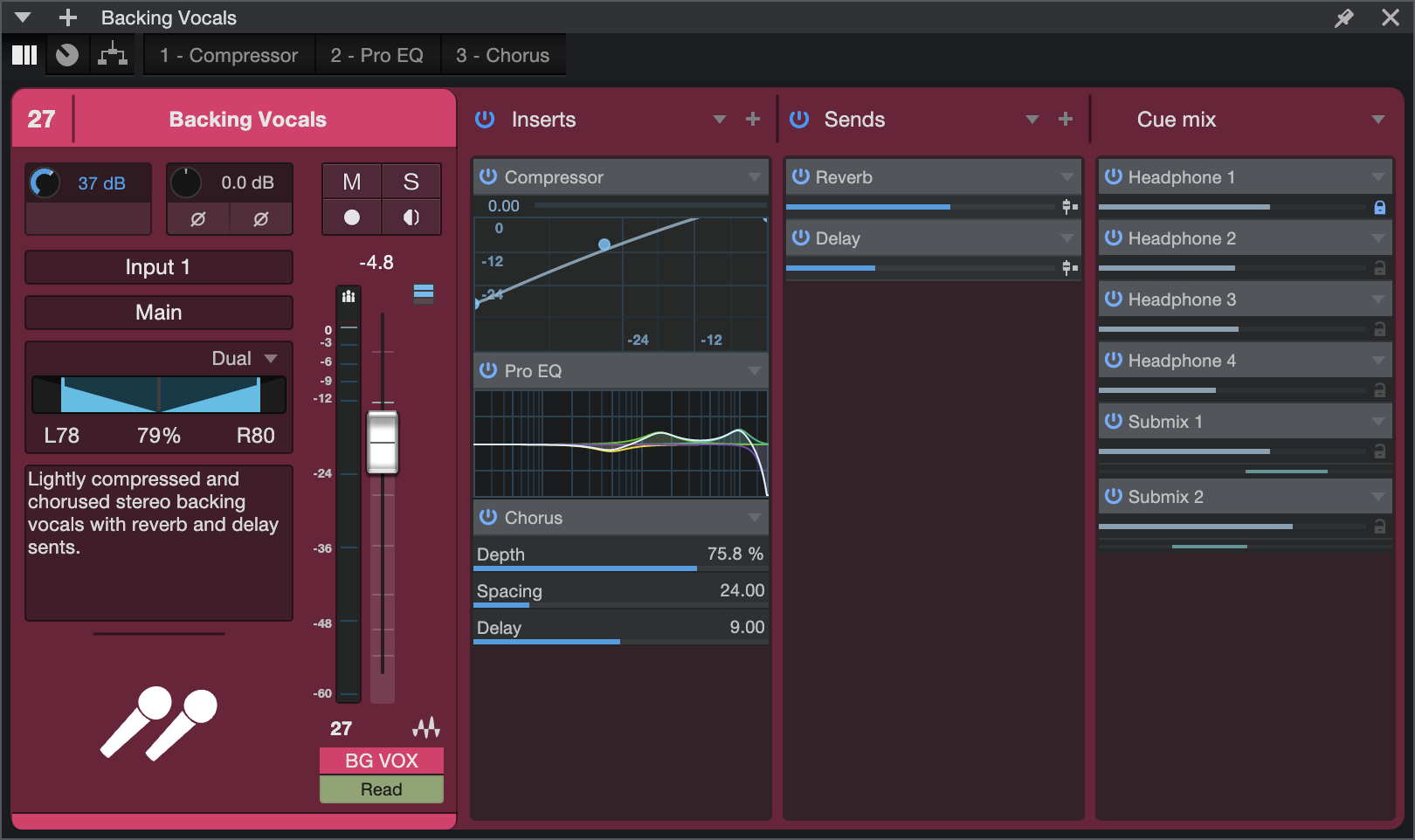
The Channel Overview Window provides a single, consolidated view of all Channel parameters, including input controls, Inserts, Sends, and Cue mix sends for the selected Channel. This view can be accessed at any time by clicking the ![]() icon from a Channel, and is also available as a tab in the Channel Editor window, next to the Macro Controls, Routing and Insert FX tabs. Channel Overview can be pinned anywhere and follows the Channel selection.
icon from a Channel, and is also available as a tab in the Channel Editor window, next to the Macro Controls, Routing and Insert FX tabs. Channel Overview can be pinned anywhere and follows the Channel selection.
For more detailed information on the features detailed below, all available from Channel Overview, we recommend first familiarizing yourself with The Console as the user interface for controlling Faders, Pans, Sends, etc. are identical in the Channel Overview.
Features of the Channel column (left) include:
- Channel number and name: Double-click the name to edit; single-click the area to select Channel color.
- Hardware Input controls: If your connected hardware supports software input controls, they will be shown here.
- Channel Input controls: Gain and Polarity. Click and drag Gain to adjust; click Polarity to toggle.
- Mute/Solo: Click either icon to toggle status.
- Record Arm/Monitor: Click either icon to toggle status.
- Input/Output routing: Click either to assign Input source our Output destination.
- Pan mode setting: Click the [▼] drop-down menu on the top left to choose from varying pan modes for stereo Tracks.
- Track Notes: Notes are displayed here. Double-click to Edit.
- Track Icon: Click here to choose or change a Track icon.
- Channel Fader and meter: Right-click the meter to choose from several metering options.
- Group assignment: Click to bring up a list of groups and re-assign the Channel, if desired.
- Automation: Click to open a list of Automation options for the Channel.
Inserts
All of the Channel’s Insert Device Racks are shown here. Channel FX Chains can be chosen, stored, enabled, and disabled from the [▼] drop-down menu icon on the top right of the Inserts column.
Effects can be added by clicking the [+] drop-down menu icon.
Devices in the Insert Device Racks can be expanded, edited, disabled, replaced, and more from their respective [▼] drop-down menus.
Sends
All of the Channel’s Insert Device Racks are shown here.
Click the [▼] drop-down menu icon on the top right of the Sends column to remove Sends or Effects Signal Routing for all Sends from the Channel’s pan setting. Alternatively, Sends can have their Channel/Pan lock settings toggled individually from their respective [▼] drop-down menus.
Sends (including Sidechain Sends), Buses, and FX Channels can be added by clicking the [+] drop-down menu icon.
Cue Mixes
All of the Channel’s Cue Mixes and Low-Latency Monitoring are shown here.
Click the [▼] drop-down menu icon on the top right of the Cue Mix column to lock/unlock Cue Mix panning from the Channel Pan setting for all Cue Mix Sends. Alternatively, Cue Mix Objects can have their Channel/Pan lock settings toggled individually from their respective drop-down menus.
Macro Controls

A single Channel in the Console can host multiple plug-in effects, and you can control them all one-by-one simply by switching from one plug-in window to another. However, in some cases, it is convenient to be able to access controls from multiple plug-ins in a central control panel. The Macro Controls feature in the Channel Editor gives you a blank canvas upon which to place crucial control parameters from any of the present effects, giving you quick access to often-needed controls. This becomes even more useful when creating FX Chain presets that are geared toward specific sounds.
For example, let's say you create an FX Chain called "Chorused Crunch Guitar Delay," that includes the Ampire, Chorus, and Analog Delay plug-ins. You might assign Macros to the gain controls on Ampire, rate and depth controls on Chorus, and the delay length and feedback on Analog Delay. In this way, as soon as you load up that FX Chain, the vital parts of its functionality become available in a central, single window, even though you're really controlling three plug-ins at once.
There are eight knobs, eight buttons, and two X/Y control pads available for each Channel. You can assign any available plug-in parameter (or multiple parameters) to each of these Macro Controls. Each control (and each axis of each X/Y pad) displays the name of the associated parameter, and the current setting of that parameter. If multiple parameters are assigned to a Macro Control, the name of the first parameter assigned is shown, with a "+" symbol next to it.
If things get complex, you can get more in-depth info about assigned parameters in the Macro Controls Mapping view.
When working with the built-in PreSonus plug-ins, assigning parameters to Macro Controls is especially easy—simply [Right]/[Ctrl]-click the control of choice, select "Connect (name of control) to Channel Macro Control" from the pop-up menu, then choose the desired Macro Control from the secondary pop-up list.
To clear all assignments for any Macro Control, [Right]/[Ctrl]-click the control and choose "Clear (control name) Connections"
Right-click a Macro Control knob or switch to get access to automation for that control.
Macro Controls Mapping
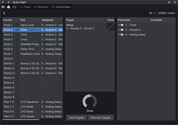
You can bring up the Macro Controls Mapping view by clicking the small wrench-shaped button in the Macro Controls window. This view gives you the ability to assign 3rd-party plug-in parameters to Macro Controls, and also provides some useful additional features for working with Macros.
The Macro Controls Mapping view shows three columns of information. The left column lists all available Macro Controls, and their current assignments (if any). The right column shows all effects plug-ins that are currently inserted into the Channel. Expand any plug-in in the list to show all assignable parameters for that plug-in. The central "Target" column is a place where Macro assignments can be made, configured, or broken.
You can assign an unlimited number of parameters to the same Macro Control, each with its own range and polarity, to create powerful “morphing controls”. As more parameters are assigned to a Macro Control, plus signs (+++) are added to the right of the default name in the Title column. You can rename the Macro Control if you like; just double-click the name in the Title column.
The simplest way to map a parameter to a Macro is to simply drag the parameter from the right column onto the Macro Control of your choice in the left column, or into the central Target column when a Macro Control is selected. You can also do this by selecting a Macro Control and a parameter, and clicking the [Add Targets] button. Once assigned, the parameter of your choice is displayed in the Target column.
To remove an assignment from a Macro Control, select the Macro in the left column, select the assignment you wish to remove in the Target column, and click the [Remove Targets] button.
Macro Control Transform Settings
You can shape the relationship between the movement of a Macro Control and the settings of its assigned parameters quite extensively. With a Macro Control selected in the left column of the Macro Controls Mapping view, the current mappings for that control are displayed in the Target column. Next to the name of each parameter is a button that gives you access to the control transform settings.
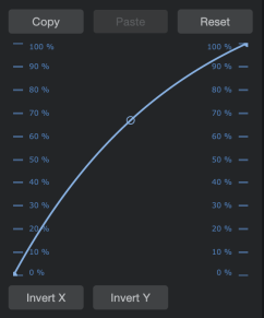
This graph traces the response curve from the beginning of the macro control's travel (the draggable point on the left end of the curve) to the end of its travel (the point on the right end), with a handle in the middle that you can drag to set the shape of the curve. Dragging these points up and down the control scales on the left and right of the graph lets you set the effective range of motion for that Macro control.
For example, the whole range of a Macro knob could be set to affect just a quarter of a parameter's range, for fine-tuning purposes. You can also move the right point below the left, reversing the action of the knob, according to whatever scale you wish.
Below the graph are buttons that let you Reset the graph to its default setting, Invert the shape of the curve, or Copy the curve setting and Paste it onto another parameter.
Note that because Macro buttons are an on-off type of control, they have no curve setting. However clicking in the Trans column next to a button assignment inverts its response, causing the parameter to be enabled when the Macro button looks disabled, and vice-versa.
Routing View
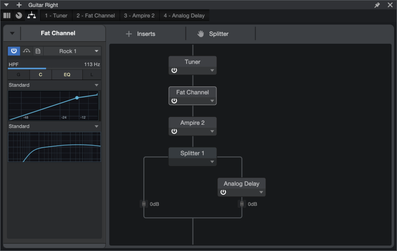
Normally, if you add multiple effects to a Channel, they are connected in series; the output of the first effect feeds into the second effect, which feeds into the third, and so on. If you open the Routing view in the Channel Editor for a Channel with multiple effects, this is what you'll see.
Each effect in the Routing view is displayed as a module. When they're in series, a line runs through them from top to bottom, signifying the path of the signal as it runs through the modules. The signal starts at the top, and flows through the effects, to the bottom.
You can click on an effects module to select it. If a selected effect is a built-in plug-in, a selection of the plug-in controls are displayed in the inspector to the left. You can load patches for the effect from this inspector, as well as set a color for the selected effects module, by clicking the color picker to the left of the effect's name in the inspector.
Each module in the Routing view has a Bypass button, as well as a drop-down menu that offers the following operations:
- Edit: Opens the editor window for the selected plug-in.
- Rename: Lets you rename the selected effect.
- Remove: Removes the selected effect from the Channel.
Adding and Moving Effects
You can add effects by dragging them into the Routing view window. Drag them into position above or below other effects to change the order in which they process the signal. You can also add effects by clicking the [Inserts] button, which brings up a menu of available effects.
Splitting Signals
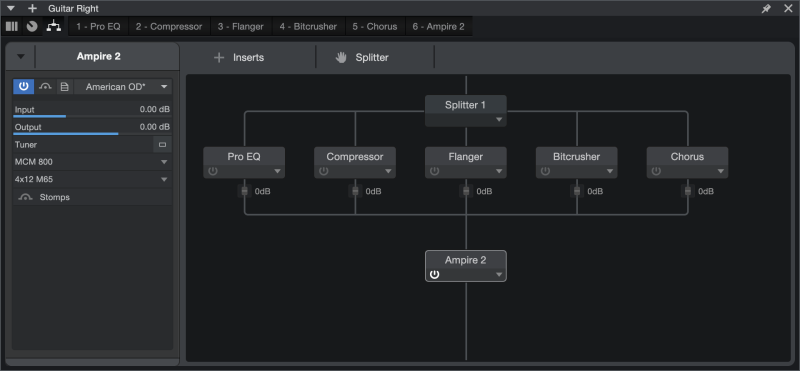
The Splitter module lets you split signals, letting you process them through multiple parallel effects paths. These split signals are then mixed back into a single signal. You can add a Splitter to your effects setup by clicking-and-dragging from the [Splitter] button to your choice of location in the Routing view.
You can click on a Splitter to select it, and its options are shown in the inspector to the left. The following options are available:
- Splits: Lets you specify the number of independent paths to split the signal into.
- Mute Output: Click the boxes to mute and unmute individual split paths.
- Levels: Lets you set the output level of each split path, from fully off (-∞ dB) to +10 dB. To set the level of a split path, simply move the corresponding slider, or click its numerical dB display to enter a value with your computer keyboard. Split path levels can also be adjusted in the Routing view. Click-and-drag the small fader icon on your chosen path to set its output level, or click in the corresponding numerical display to enter a value in dB.
- Split Mode: Select the Splitter mode that suits your needs, from the following choices:
- Normal: Splits the signal into two or more identical copies. This is useful for any sort of parallel processing, such as "New York" compression or vocal multiprocessing.
- Channel Split: Splits multichannel signals into pairs of mono signals, for independent processing of left and right channel information. (E.g. With two splits, this turns a stereo signal into a pair of left/right mono signals. With four splits, you get two sets of left-right mono signals.
- Frequency Split: Splits a signal into isolated bands of frequencies, at the frequencies you specify. With two splits, the signal is crossed-over into two frequency bands, split at a single frequency. With three splits, there are three bands, split at two crossover frequencies, and so on. When more than one frequency split is employed, The splits are numbered from low frequency to high.
Much like you can move effects modules into different places in the signal chain, you can move Splitter modules to the position of your choice, as well as freely move effects into and out of each split path. To remove a Splitter module, click its triangle to open the pop-up menu and choose Remove. If you remove a splitter module that has effects inserted within its split signals, those effects are reconnected in series.
Splitter effects chains are compensated for plug-in delay automatically, retaining the proper time relationship between all split channels.
Quick Access to Main Bus Inserts
To quickly open the Channel Editor for the Main output bus, double-click the main output meters in the Transport bar.